Traffic barrier - TB
These plans provide the necessary details to fabricate, construct and install traffic barriers. Note that the use of all Traffic Barrier-TB plans is restricted to WSDOT internal use only. Contact HQ Design for more details.
Traffic Barrier - TB
You will find the following plans for all Traffic Barrier - TB. These plans provide the necessary details to fabricate, construct and install traffic barriers.
- Beam Guardrail (Thrie Beam) (TB-100)
- Beam Guardrail Transition - (Posted Speed 45 mph or Below) (TB-2)
- Beam Guardrail (Type 31) Anchor Type 10 (TB-126)
- Low Speed Concrete Barrier Terminal (TB-4)
- Low Profile Barrier (TB-13 - TB-21)
- Precast Concrete Barrier Anchor Type 3 (Permanent) (TB-104)
- Precast Concrete Barrier Transition - Type 2 to Precast Single Slope (TB-23)
- Concrete Barrier Transition - Type 2 to CIP Single Slope (TB-114)
- Concrete Barrier Transition - Type 2 to Bridge F-Shape (TB-106)
- Steel-backed Timber Guardrail (TB-25, TB-26, TB-27, & TB-28)
- Type 3 Guardrail Anchor Retrofit for Thrie Beam (TB-50)
You will also find TB – Old Type 1 Barriers. Details and plans are provided for information only. Type 1 guardrails are no longer used by WSDOT for new installations.
- Type 20 and Type 21 Guardrail and Type 6 Transitions (TB-55, TB-56, TB-C3a)
- (Old) Type 1 Beam Guardrail Placement Cases (TB-C2, TB-C2a, TB-C2b, TB-C2d, TB-C2g, TB-C2i, TB-C2k, TB-C2n, TB-C2p)
- (Old) Type 1 Beam Guardrail Systems - Beam Guardrail Type 1 - Buried Terminal Type 1 (TB-10) and Beam Guardrail Type 1 - Buried Terminal Type 2 (TB-C-22.14)
- (Old) Type 1 Guardrail - Flared Terminals (TB-C4b)
- (Old) Type 1 Guardrail - Non-Flared Terminals (TB-C4e)
- (Old) Type 1 Beam Guardrail Transitions (TB-C3, TB-C3a, TB-C3b, TB-C3c)
- (Old) Type 1 Beam Guardrail Anchors (TB-C6, TB-C6c, TB-C6d, TB-C6f)
- (Old) Beam Guardrail Types 1-4 (TB-C1)
- Beam Guardrail Type 1 Components, Beam Guardrail Posts and Blocks, Beam Guardrail End Sections, Thrie Beam End Sections (TB-108, TB-120, TB-122, TB-124)
- Thrie Beam Transition Type 1B (TB-C301)
- (Old) Type 1 Beam Guardrail – Guardrail Installation on a Box Culvert (TB-C10)
Beam Guardrail (Thrie Beam) (TB-100)
This plan provides the necessary details to construct the thrie beam guardrail system (Beam Guardrail Types 10 and 11). The thrie beam guardrail system is a stronger version of the W-Beam guardrail system. The additional corrugation (3-corrugations) in the thrie beam guardrail system stiffens the system, making it less prone to damage during low and moderate speed vehicle impacts.
View Beam Guardrail (Thrie Beam) (TB-100) plan sheet (PDF 1.3MB)
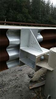
Beam Guardrail Transition - (Posted Speed 45 mph or Below) (TB-2)
This plan is intended to depict a Beam Guardrail Transition system used to transition from Beam Guardrail Type 31 to another structure. This System could be used where there is limited length available and a Standard Transition will not fit. This Transition section consists of an End Section Design F, with a Thrie Beam Rail Section, and Reducer Section Type C.
View Beam Guardrail Transition (TB-2) plan sheet (PDF 745KB)
Beam Guardrail (Type 31) Anchor Type 10 (TB-126)
This plan provides the necessary details to construct the Type 10 anchor. In September 2022, the MASH crash tested Type 11 anchor (Std. Plan C-23.70) took the place of the Type 10 anchor as an option to terminate Type 31 guardrail runs. The Type 10 anchor is used to terminate Type 31 guardrail runs at locations where the end of the run is located outside the Design Clear Zone and/or not subject to head-on impacts. For new installations, the Type 10 anchor is no longer an option. However, it is acceptable to leave functional existing Type 10 anchors in place in existing Type 31 guardrail runs.
View Beam Guardrail (Type 31) Anchor Type 10 (TB-126) plan sheet (PDF 2.3MB)
Low Speed Concrete Barrier Terminal (TB-4)
This plan provides the necessary details to construct the low speed concrete barrier terminal noted in the WSDOT Design Manual Chapter 1610.
This terminal can be used as an end treatment for Type 2 Concrete Barrier on roadways with a posted speed of 35 mph or less.
These terminals are used infrequently, and concrete products companies willing to do the work inexpensively may be difficult to locate. The initial cost for this terminal might be as high as a manufactured impact attenuator; however, long-term maintenance costs will be significantly less.
View Low Speed Concrete Barrier Terminal (TB-4) plan sheet (PDF 660KB)
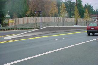
Low Profile Barrier (TB-13 - TB-21)
These drawings provide details to construct a Low Profile Barrier. This design may be used for raised medians where the posted speed is 45 mph or less. The barrier shape is designed to redirect vehicles, reducing the risk of vehicle median crossovers.
This design may also serve as a substitute for vertical or mountable curb in medians when access across the median is undesirable. The raised area behind the barrier can be either paved or used for landscaping.
View Low Profile Barrier (TB-13) plan sheet (PDF 1.45MB)
View Low Profile Barrier Type 2 (TB-14) plan sheet (PDF 1.41MB)
View Low Profile Barrier Type 3 (TB-15) plan sheet (PDF 1.54MB)
View Low Profile Barrier Nose (TB-16) plan sheet (PDF 1.51MB)
View Type 1 Low Profile Barrier transition to Traffic Curb (TB-17) plan sheet (PDF 1.27MB)
View Type 2 Low Profile Barrier transition to Traffic Curb (TB-18) plan sheet (PDF 1.33MB)
View Low Profile Barrier Placement (Precast) (TB-19) plan sheet (PDF 2.16MB)
View Low Profile Barrier Placement (Cast in place) (TB-20) plan sheet (PDF 1.78MB)
View Low Profile Barrier Placement with Traffic Curb Nose (TB-21) plan sheet (PDF 1.4MB)
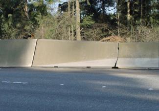
Precast Type 2 (NJ) Concrete Barrier (TB-104, TB-23, TB-114, TB-106)
The following plans provide details to construct specialized configurations of the Type 2 concrete barrier. The Type 2 concrete barrier system utilizes a New Jersey safety shape and is the old precast concrete barrier system previously used by WSDOT before moving to F-Shape barrier system. Type 2 concrete barrier can be used in roadside and median applications. Permanent installations of Type 2 concrete barrier are placed on paved asphalt or concrete surfaces with the paving extending behind the barrier. The Type 2 concrete barrier system can be used in free-standing or anchored configurations. See Standard Plans K-80.32 and K-80.34 for the standard dual-sided and vertical back barrier section details. See Standard Plans K-80.35 and K-80.37 for temporary anchoring of Type 2 barrier.
Precast Concrete Barrier Anchor Type 3 (Permanent) (TB-104)
This plan shows details necessary to permanently anchor the Type 2 concrete barrier on HMA pavement.
View Precast Concrete Barrier Anchor Type 3 (Permanent) (TB-104) plan sheet (PDF 708KB)
Precast Concrete Barrier Transition - Type 2 to Precast Single Slope (TB-23), Concrete Barrier Transition Type 2 to CIP Single Slope (TB-114), Concrete Barrier Transition Type 2 to Bridge F-Shape (TB-106)
These drawings show the details necessary to construct a precast transition for a Type 2 concrete barrier to a precast single slope concrete barrier. A CIP transition for a Type 2 concrete barrier to a CIP single slope concrete barrier, and a CIP transition for a Type 2 concrete barrier to bridge F-Shape barrier. These transition barriers require installation below the finished pavement. These are commonly used when connecting a new run of single slope barrier to the older Type 2 (New Jersey shaped) concrete barrier or connecting the older Type 2 concrete barrier to bridge F-Shape barrier.
View Precast Concrete Barrier Transition - Type 2 to Single Slope plan sheet (TB-23) (PDF 755KB)
View Concrete Barrier Transition - Type 2 to CIP Single Slope (TB-114) plan sheet (PDF 694KB)
View Concrete Barrier Transition Type 2 to Bridge F-Shape (TB-106) plan sheet (PDF 891KB)
Steel-backed Timber Guardrail (TB-25, TB-26, TB-27, & TB-28)
These plans show all the details necessary to fabricate this barrier system.
This guardrail system may be used on designated scenic byways and heritage tour routes if funding can be arranged.
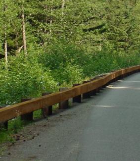
The Steel-backed Timber Guardrail system consists of a timber rail with a steel plate attached to the back to increase its tensile strength.
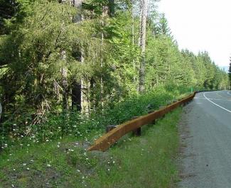
The most desirable method of terminating a run of Steel-backed Timber Guardrail is with a buried terminal in a backslope. When this is not feasible, the system is limited to use on highways with a posted speed of 45 mph or less, and the barrier run is required to flare away from the traveled way and terminate in a berm.
View Posted Steel-backed Timber Guardrail (TB-25) plan sheet (PDF 770KB)
View Posted Steel-backed Timber Guardrail Buried Anchor (TB-26) plan sheet (PDF 789KB)
View Steel-backed Timber Guardrail Non-flared Terminal (TB-27) plan sheet (PDF 1.2MB)
View W-Beam to timber Guardrail Transition (TB-28) plan sheet (PDF 844KB)
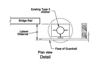
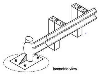
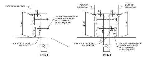
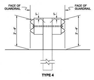
Type 3 Guardrail Anchor Retrofit for Thrie Beam (TB-50)
The old Type 3 anchor was primarily used at bridge ends. This anchor consisted of a steel pipe mounted vertically in a concrete foundation. Bridge approach guardrail was then mounted on the steel pipe.
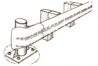
On one-way highways, these anchors were usually positioned so that neither the anchor nor the bridge rail posed a snagging potential. When these cases are encountered, the anchor may remain in place if a stiffened transition section is provided at the connection to the post.
On two-way highways, the anchor may present a snagging potential. In these cases, install this retrofit connection from the anchor to the bridge rail if the offset from the bridge rail to the face of the guardrail is 1 foot 6 inches or less. If the offset is greater than 1 foot 6 inches, remove the anchor and install a new transition and connection.
There are two designs to choose from. Select the retrofit detail that is appropriate for achieving the desired rail height.
Before including these details in the Contract Documents, contact:
Bill Berens
HQ Design Office
Bill.Berens@wsdot.wa.gov
360-705-7256
View Type 3 Guardrail Anchor Retrofit for Thrie Beam plan sheet (PDF 680KB)
Download free Adobe Acrobat Reader
Download free evaluation version of WinZip
TB – Old Type 1 Barriers
These details and plans are provided for information only. Type 1 guardrails are no longer used by WSDOT for new installations.
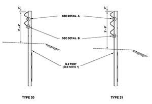
Type 20 and Type 21 Guardrail and Type 6 Transitions
Used with Service Level 1 Bridge Rail
The systems shown do not currently meet MASH requirements.
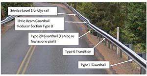
Type 20 and Type 21 guardrail are primarily used in conjunction with Service Level 1 bridges. Type 20 and Type 21 guardrail are TL-2 systems appropriate for speeds 45 mph or less.
Service Level 1 Bridge Rail
This design has been utilized on some short concrete spans and timber bridges. A failure mechanism is built into this rail system so that upon impact the post will break away from the mounting bracket, ensuring minimal damage to the bridge. The thrie beam guardrail will contain the vehicle. Contact the Bridge & Structures Office for more information about Service Level 1 bridges.
For Type 20 guardrail and Type 21 guardrail, see (TB-55) Beam Guardrail Type 20 & 21 (PDF 632KB), formerly Standard Plan C-1c.
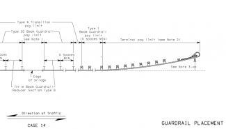
Placement Case 14 applies to Service Level 1 bridge rail systems. Type 20 guardrail is used on the approach and no transition is needed between the Type 20 guardrail and the Service Level 1 bridge rail since they are both weak post systems. For Placement Case 14, see (TB-56) Guardrail Placement Case 14 for Type 20 Guardrail (PDF 638KB), formerly Standard Plan C-2h.
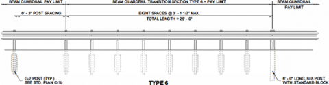
A Type 6 transition (shown below) is used when connecting Type 20 guardrail to a strong post (Type 31) guardrail or a terminal. The Type 6 transition is needed to transition from the flexible Type 20 to the stiffer Type 31 guardrail.
For the Type 6 transition, see (TB-C3a) Type 1 Beam Guardrail Transition Sections (PDF 671KB) (Types 2, 4, 5, & 6)
(Old) Type 1 Beam Guardrail Placement Cases
Previously, WSDOT standard practice was to install W-beam guardrail at a rail height of 27 to 28 inches, referred to as “Type 1” guardrail. WSDOT introduced Type 31 guardrail in 2009 as the replacement for Type 1 guardrail. Type 1 guardrail is no longer used by WSDOT for new installations.
The following information and plans are provided for information only.
- Case 1 is used where there is one-way traffic. It uses a crash-tested terminal on the approach end and a Type 4 anchor on the trailing end. See (TB-C2) Type 1 Guardrail Placement (PDF 663KB), formerly Standard Plan C-2.
- Case 2 is used where there is two-way traffic. A crash-tested terminal is used on both ends. When flared terminals are used on both ends, use a minimum of 25 feet of guardrail between the terminal limits when feasible. See (TB-C2) Type 1 Guardrail Placement (PDF 663KB), formerly Standard Plan C-2.
- Case 3 is used at railroad signal supports on one-way or two-way roadways. A terminal is used on the approach end, but usually cannot be used on the trailing end because of its proximity to the railroad tracks. If there is a history of crossover collisions, consider additional protection such as an impact attenuator. See (TB-C2) Type 1 Guardrail Placement (PDF 663KB), formerly Standard Plan C-2.
- Case 4 is used where guardrail on the approach to a bridge is to be shifted laterally to connect with the bridge rail. A terminal is used on the approach end and a transition is needed at the bridge end. A curve in the guardrail is shown to shift it to the bridge rail. However, the length of the curve is not critical. The criterion is to provide a smooth curve that is not more abrupt than the allowable flare rate (see Chapter 1610 for the flare rate). See (TB-C2a) Type 1 Guardrail Placement Cases 4, 5 and 6 (PDF 679KB), formerly Standard Plan C-2a.
- Case 5 is a typical bridge approach where a terminal and a transition are needed. See (TB-C2a) Type 1 Guardrail Placement Cases 4, 5 and 6 (PDF 679KB), formerly Standard Plan C-2a.
- Case 6 is used on bridge approaches where opposing traffic is separated by a median that is 36 feet or wider. This case is designed so that the end of the guardrail will be outside the Design Clear Zone for the opposing traffic. See (TB-C2a) Type 1 Guardrail Placement Cases 4, 5 and 6 (PDF 679KB), formerly Standard Plan C-2a.
- Cases 7 and 8 are used with beam guardrail median barrier when median fixed features such as bridge piers are encountered. A transition is needed on the approach end for each direction, and the flare rate is not to be more abrupt than the allowable flare rate (see Chapter 1610 for the flare rate). See (TB-C2b) Type 1 Guardrail Placement Cases 7 and 8 (PDF 679KB), formerly Standard Plan C-2b.
- Case 10 (A, B, and C) is used at roadside fixed features (such as bridge piers) when 3 or more feet are available from the face of the guardrail to the object. The approach end is the same for one-way or two-way traffic. Case 10A is used with two-way traffic; therefore, a terminal is needed on the trailing end. Case 10B is used for one-way traffic when there is no need to extend guardrail past the bridge pier and a Type 4 anchor is used to end the guardrail. Case 10C is used for one-way traffic when the guardrail will extend for a distance past the bridge pier. See (TB-C2d) Type 1 Guardrail Placement Case 10a, 10b, 10c (PDF 652KB), formerly Standard Plan C-2d.
- Case 11 (A, B, and C) is used at roadside fixed features (such as bridge piers) when the guardrail is to be placed within 3 feet of the object. Since there is no room for deflection, the rail in front of the feature is to be considered a rigid system and a transition is needed. The trailing end cases are the same as described for Case 10. See (TB-C2e) Type 1 Guardrail Placement Case 11a. 11b, 11c (PDF 652KB), formerly Standard Plan C-2e.
- Cases 12 and 13 are called “Weak Post Intersection Designs.” They are used where an intersection design needs a gap in the guardrail or there is not adequate space for a bridge approach installation that includes a transition, a terminal, or both. These placements are designed to collapse when hit at the nose, and the ribbon strength of the rail brings the vehicle to a stop. A Type 7 anchor is used to develop the ribbon strength. These designs include a Type 5 transition for connection with bridge rail and a Type 5 anchor at the other end of the rail. The Type 5 anchor is not a breakaway anchor and therefore can typically be used only in situations where a crash-tested terminal is not needed; for example, where slow-moving vehicles are anticipated, such as some side roads and driveways. (See (TB-C2f) Type 1 Guardrail Placement - Weak post intersection design (PDF 712KB) & (TB-C2g) Type 1 Guardrail Placement - Weak post intersection design (35' max radius) (PDF 727KB), formerly Standard Plans C-2f & C-2g.
- Since an impacting vehicle might penetrate into the system, it is critical that no fixed feature be located within the clear area shown in the Plan. The 25 feet of barrier length beyond the PC along the side road are critical for the operation of this system. These designs were developed for intersections that are approximately perpendicular. Evaluate installation on skewed intersections on a case-by-case basis. Use the Case 22 placement if it is not feasible to install this design according to the Plan.
- Case 15 is used to carry guardrail across a box culvert where there is insufficient depth to install standard posts for more than 17 feet 8 inches. This design uses steel posts anchored to the box culvert to support the rail. Newer designs—Cases 19, 20, and 21—have replaced this design for shorter spans. See (TB-C2i) Type 1 Guardrail Placement Case 15 (PDF 635KB), formerly Standard Plan C-2i.
- Cases 16 and 17 are similar to Cases 1 and 2, except that they flare the rail and terminal as far from the road as possible and reduce the length of need. See (TB-C2j) Type 1 Guardrail Placement Case 16, 17, and 18 (PDF 635KB), formerly Standard Plan C-2j.
- Case 18 is used on the trailing end of bridge rail on a one-way roadway. No transition is needed. See (TB-C2j) Type 1 Guardrail Placement Case 16, 17, and 18 (PDF 65KB), formerly Standard Plan C-2j.
- Case 19 (A and B) is used where it is not possible to install a post at the 6-foot 3-inch spacing. This design omits one post (resulting in a span of 11 feet 6 inches, which is consistent with a post spacing of 12 feet 6 inches) and uses nested W-beam to stiffen the rail. The cases differ by the location of the splice. No cutting of the rail or offsetting of the splices is needed or desirable. See (TB-C2k) Type 1 Guardrail Placement 12' - 6' Span (PDF 635KB), formerly Standard Plan C-2j.
- Case 20 is similar to Cases 19A and 19B, except that it allows for two posts to be omitted, which results in a span consistent with post spacing of 18 feet 9 inches. See (TB-C2n) Type 1 Guardrail Placement 18' - 6" Span (PDF 635KB), formerly Standard Plan C-2n.
- Case 21 has a similar intent as Cases 19A, 19B, and 20 in that it allows for the omission of posts to span an obstruction. This design uses CRT posts with additional post blocks for three posts before and after the omitted posts. The design allows for three posts to be omitted, which results in a span consistent with a post spacing of 25 feet. See (TB-C2o) Type 1 Guardrail Placement 25' Span (PDF 653KB), formerly Standard Plan C-2o.
- Case 22 is the “Strong Post Intersection Design” that provides a stiff barrier. This design is to be used as a last resort at crossroads or road approaches where a barrier is needed and there isn’t a clear area behind the nose or minimum distances for a “Weak Post Intersection Design” (see Cases 12 and 13). See (TB-C2p) Type 1 Guardrail Placement 25' Span (PDF 676KB), formerly Standard Plan C-2p.
(Old) Type 1 Beam Guardrail Systems
Previously, WSDOT standard practice was to install W-beam guardrail at a rail height of 27 to 28 inches, referred to as “Type 1” guardrail. WSDOT introduced Type 31 guardrail in 2009 as the replacement for Type 1 guardrail. Type 1 guardrail is no longer used by WSDOT for new installations. The following information and plans are provided for information only.
Buried Terminals for Type 1 Guardrail
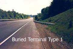
A buried terminal (BT) is designed to terminate the guardrail by burying the end into the backslope. The BT is the preferred terminal because it eliminates the exposed end of the guardrail and provides full shielding of the identified feature.
If a MASH compliant buried terminal is required for an existing guardrail run, use the buried terminal design for Type 31 guardrail and use the Type 31 to Type 1 adaptor.
The Buried Terminal uses a Type 2 anchor to develop the tensile strength in the guardrail. The backslope needed to install a BT is to be 3H:1V or steeper and at least 4 feet in height above the roadway. If the backslope is flatter than 1H:1V, provide a minimum 20-foot-wide by 75-foot-long distance behind the barrier and between the beginning length of need point at the terminal end to the mitigated object to be protected.
Flare the guardrail to the foreslope/backslope intersection using a flare rate that meets the criteria in 1610.04(5)(a). Provide a 4H:1V or flatter foreslope into the face of the guardrail and maintain the full guardrail height to the foreslope/backslope intersection in relation to a 10H:1V line extending from edge of shoulder breakpoint.
Length of need: The entire BT can be used within the length of need for backslopes of 1H:1V or steeper if the barrier remains at full height in relation to the roadway shoulder to the point where the barrier enters the backslope. For backslopes between 1H:1V and 3H:1V, design the length of need beginning at the point where the W-beam remains at full height in relation to the roadway shoulder - usually beginning at the point where the barrier crosses the ditch line.
Beam Guardrail Type 1 - Buried Terminal Type 1 (TB-10) and Beam Guardrail Type 1 - Buried Terminal Type 2 (TB-C-22.14)
These plans depict the details necessary to provide a Beam Guardrail Type 1 - Buried Terminal Type 1 (formerly Std. Plan C-4) or a Beam Guardrail Type 1 - Buried Terminal Type 2 (formerly Std. Plan C-22.14).
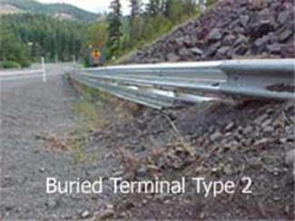
The Beam Guardrail Type 1 - Buried Terminal Type 1 and the Beam Guardrail Type 1 - Buried Terminal Type 2 were previously available options for consideration to be used with beam guardrail runs.
For new installations, these are no longer an option. It is acceptable to leave a Beam Guardrail Type 1 -Buried Terminal Type 1 or Beam Guardrail Type 1 - Buried Terminal Type 2 in service for existing situations if no work is required to the existing barrier run.
View Beam Guardrail Type 1 - Buried Terminal Type 1 (TB-10) plan sheet (PDF 698KB)
View Beam Guardrail Type 1 - Buried Terminal Type 2 (TB-C-22.14) plan sheet (PDF 755KB)
(Old) Type 1 Guardrail - Flared Terminals
Informational only - The terminals shown on these plans are the terminals that were on the WSDOT Qualified Products List at the time of the specification change requiring MASH compliance for Type 1 guardrail terminals (April 2018). The terminals shown are not MASH compliant. The plans are provided for information only. See (TB-C4b) Type 1 Beam Guardrail Flared Termina1 (PDF 673KB), formerly Standard Plan C-4b.
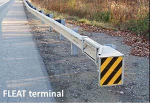
Image from Road Systems website
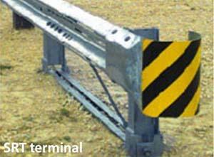
Image from Trinity website
Flared terminal designs were used with Type 1 guardrail. The Slotted Rail Terminal (SRT) and the Flared Energy Absorbing Terminal (FLEAT) are two examples. With flared terminals it is important that the embankment quantity also be specified so that the area around the terminal can be constructed as shown in the Plans.
SRT terminal
The SRT uses W-beam guardrail with slots cut into the corrugations and posts throughout the length of the terminal. The end of the SRT is offset from the tangent guardrail run by the use of a parabolic flare. When struck head on, the first two posts are designed to break away, and the parabolic flare gives the rail a natural tendency to buckle, minimizing the possibility of the guardrail end entering the vehicle. The buckling is facilitated by the slots in the rail. The remaining posts provide strength to the system for redirection and deceleration without snagging the vehicle. The SRT has a 4-foot offset at the first post.
The SRT terminal can be supplied with wood or steel posts. Match the type of SRT posts with those of the longitudinal barrier run to which the terminal will be connected.
FLEAT terminal
The FLEAT uses W-beam guardrail with a special end piece that fits over the end of the guardrail and posts. The end of the FLEAT is offset from the tangent guardrail run by the use of a straight flare. When struck head on, the end piece is forced over the rail, bending the rail and forcing it away from the impacting vehicle.
The FLEAT is available in two designs based on the posted speed of the highway. For highways with a posted speed of 50 mph or above, use a FLEAT 350, which has a 4-foot offset at the first post. For highways with a posted speed of 45 mph or below, use a FLEAT TL-2, which has a 1-foot 8-inch offset at the first post. The FLEAT terminal can be supplied with wood or steel posts. Match the type of FLEAT posts with those of the longitudinal barrier run to which the terminal will be connected.
Length of need
The length of need begins at the third post for both flared terminals.
(Old) Type 1 Guardrail - Non-Flared Terminals
Informational only - The terminal shown on this plan is the terminal that was on the WSDOT Qualified Products List at the time of the specification change requiring MASH compliance for Type 1 guardrail terminals (April 2018). The terminal shown is not MASH compliant. The plan is provided for information only. These systems use W-beam guardrail with a special end piece that fits over the end of the guardrail. When hit head on, the end piece is forced over the rail, absorbing the energy of the impacting vehicle in the process. An anchor is typically included for developing the tensile strength of the guardrail.
Non-flared terminals may be provided for two different design levels which are based on the posted speed of the highway. For highways with a posted speed of 50 mph or above, use only a TL-3 (Test Level 3) product. For highways with a posted speed of 45 mph or below, either a TL-2 or a TL-3 product is acceptable.
Although non-flared terminals do not need to have an offset at the end, a flare is recommended so that the end piece does not protrude into the shoulder. See the Plans.
Four feet of widening is needed at the end posts to properly anchor the systems. When widening includes an embankment, fill material will be necessary for optimum terminal performance (see the Plans).
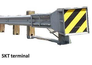
One proprietary terminal is the Sequential Kinking Terminal (SKT). This terminal is available in two designs based on the posted speed of the highway. The primary difference in these designs is the length of the terminal. For highways with a posted speed of 50 mph or above, use the 50-foot-long SKT 350 (TL-3) terminal. For highways with a posted speed of 45 mph or below, use the 25-foot-long SKT-350 (TL-2).
Length of need
The length of need does not begin at the impact head, but will vary by system.
See (TB-C4e) Type 1 Beam Guardrail Non-Flared Terminal (PDF 661KB), formerly Standard Plan C-4e.
(Old) Type 1 Beam Guardrail Transitions
Previously, WSDOT standard practice was to install W-beam guardrail at a rail height of 27 to 28 inches, referred to as “Type 1” guardrail. WSDOT introduced Type 31 guardrail in 2009 as the replacement for Type 1 guardrail. Type 1 guardrail is no longer used by WSDOT for new installations. The following information and plans are provided for information only.
When there is an abrupt change from one barrier type to a more rigid barrier type, a vehicle hitting the more flexible barrier may be caught in the deflected barrier pocket and directed into the more rigid barrier. This is commonly referred to as “pocketing.” A transition stiffens the more flexible barrier by decreasing the post spacing, increasing the post size, and using stiffer beam elements to reduce the possibility of pocketing.
Note: WSDOT introduced Type 31 guardrail in 2009 as the replacement for Type 1 guardrail. The guidance in the Design Manual regarding guardrail transitions was updated in 2009 to show Type 31 guardrail transitions instead of Type 1 guardrail transitions. As such, the May 2008 version of the Design Manual was the last Design Manual version to show complete guidance regarding transitions for Type 1 guardrail.
| Transition Type | Plan Sheet | Formerly Standard Plan | ||
| 1, 1A | * TB-C3 - Type 1 Beam Guardrail Transition Sections (Types 1 & 1A)(PDF 710KB) | C-3 | ||
| 4, 5, 6 | TB-C3a - Type 1 Beam Guardrail Transition Sections (Types 2, 4, 5, & 6)(PDF 670KB) | C-3a | ||
| 10, 11, 12 | TB-C3b - Type 1 Beam Guardrail Transition Sections (Types 10 ~ 15)(PDF 820KB) | C-3b | ||
| 13, 14, 15 | TB-C3b - Type 1 Beam Guardrail Transition Sections (Types 10 ~ 15)(PDF 820KB) | C-3b | ||
| 16, 17, 18 | TB-C3c - Type 1 Beam Guardrail Transition Sections (Types 16, 17, & 18)(PDF 709KB) | C-3c |
* See Detail Type E ~ Guardrail Connection to Bridge Rail or Concrete Barrier for 'E" Connection Option (PDF 710KB) for TB-C-3, Type 1A.
(Old) Type 1 Beam Guardrail Anchors
Previously, WSDOT standard practice was to install W-beam guardrail at a rail height of 27 to 28 inches, referred to as “Type 1” guardrail. WSDOT introduced Type 31 guardrail in 2009 as the replacement for Type 1 guardrail. Type 1 guardrail is no longer used by WSDOT for new installations. The following information and plans are provided for information only.
A guardrail anchor is needed at the end of a run of guardrail to develop tensile strength throughout its length.
Type of anchors
Type 1 anchors are used for (Old) Beam Guardrail Type 1 runs and can be used on either the upstream or downstream end located beyond the clear zone where a crash-tested terminal is not needed. See (TB-C6) Beam Guardrail Type 1 Anchor (PDF 728KB), formerly Standard Plan C-6.
The Type 3 anchor was primarily used at bridge ends (see below). This anchor consisted of a steel pipe mounted vertically in a concrete foundation. Bridge approach guardrail was then mounted on the steel pipe.
On one-way highways, these anchors were usually positioned so that neither the anchor nor the bridge rail posed a snagging potential. When these cases are encountered, the anchor may remain in place if a stiffened transition section is provided at the connection to the post.
On two-way highways, the anchor may present a snagging potential. In these cases, install a connection from the anchor to the bridge rail if the anchor’s lateral offset from the bridge rail to the face of the guardrail is 1-foot 6-inches or less. If the offset is greater than 1-foot 6-inches, remove the anchor and install a new transition and connection.
No plan is available for the Type 3 anchor. Also see TB50 for additional information.
Type 4 anchors are used for (Old) Beam Guardrail Type 1 where a crash-tested terminal is not needed. See (TB-C6c) Beam Guardrail Type 4 Anchor (PDF 670KB), formerly Standard Plan C-6c.
Type 5 anchors are used for (Old) Beam Guardrail Type 1 with the Weak Post Intersection Design, see placement cases 12 and 13. See (TB-C6d) Beam Guardrail Type 5 Anchor (PDF 669KB), formerly Standard Plan C-6d.
Type 7 anchors are used for (Old) Beam Guardrail Type 1 to develop tensile strength in the middle of a guardrail run when the guardrail curves and weak posts are, see placement cases 9, 12, and 13. See (TB-C6f) Beam Guardrail Type 7 Anchor (PDF 638KB), formerly Standard Plan C-6f.
(Old) Beam Guardrail Types 1-4
Previously, WSDOT standard practice was to install W-beam guardrail at a rail height of 27 to 28 inches, referred to as “Type 1” guardrail. WSDOT introduced Type 31 guardrail in 2009 as the replacement for Type 1 guardrail. Type 1 guardrail is no longer used by WSDOT for new installations. The following information and plans are provided for information only.
Type 1 Guardrail has a height of 27 to 28 inches, utilizes 8” block-outs, and the bolts that connect rail elements (rail splices) are located at the posts. See (TB-C1) Beam Guardrail Types 1-4 (W beam)(PDF 887KB), formerly Standard Plan C-1.
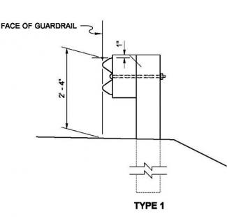
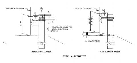
“Type 1 Alternate” guardrail is a version of Type 1 guardrail that has holes pre-drilled to allow raising of the blocks and rail element after a future overlay. See (TB-C1) Beam Guardrail Types 1-4 (W beam)(PDF 887KB), formerly Standard Plan C-1.
W-beam guardrail Type 2 and Type 3 have a height of 30 inches and utilize a rubrail. A rubrail is a structural steel channel added below the W-beam rail and is used in these specific designs to reduce vehicle snagging on the post. See (TB-C1) Beam Guardrail Types 1-4 (W beam) (PDF887KB), formerly Standard Plan C-1.
Type 4 guardrail is a double-sided version of the Type 1 guardrail system. For new installations WSDOST uses the Type 31 double-sided w-beam guardrail instead of Type 4 guardrail. See (TB-C1) Beam Guardrail Types 1-4 (W beam) (PDF 887KB), formerly Standard Plan C-1.
Beam Guardrail Components (TB-108), Beam Guardrail Posts and Blocks (TB-120), Beam Guardrail End Sections (TB-122) and Thrie Beam End Sections (TB-124)
These plans show component details needed for guardrail/thrie beam systems including rail elements and channel rail splices (TB-108), varying types of posts and blocks (TB-120), W-beam guardrail end sections (TB-122), and thrie beam end sections (TB-124).
View Beam Guardrail Type 1 Components (TB-108) plan sheet (PDF 88KB)
View Beam Guardrail Posts and Blocks (TB-120) plan sheet (PDF 836KB)
View Beam Guardrail End Sections (TB-122) plan sheet (PDF 701KB)
View Thrie Beam End Sections (TB-124) plan sheet (PDF 80KB)
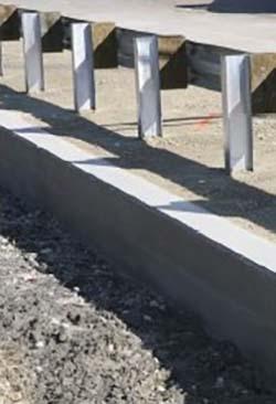
Thrie Beam Transition Type 1B
This transition is used to connect thrie beam to a rigid barrier.
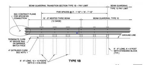
See (TB-C301) Thrie Beam Transition Type 1B (PDF 629KB), formerly Standard Plan C-3.
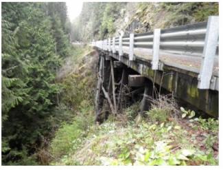
(Old) Type 1 Beam Guardrail – Guardrail Installation on a Box Culvert
Previously, WSDOT standard practice was to install W-beam Type 1 guardrail on top of a concrete box culvert at a rail height of 27 to 28 inches utilizing steel posts anchored to the box culvert. WSDOT introduced Type 31 guardrail in 2009 as the replacement for Type 1 guardrail. Type 1 guardrail is no longer used by WSDOT for new installations. The following information and plans are provided for information only.
Type 1 Guardrail on a Concrete Box Culvert
Guardrail installations along the roadway may require placement over an existing or new reinforced concrete box culvert.
See (TB-C10) Box Culvert Guardrail Steel Post (PDF 799KB), formerly Standard Plan C-10.
Download free Adobe Acrobat Reader
Download free evaluation version of WinZip
Slow down – lives are on the line.
In 2023, speeding continued to be a top reason for work zone crashes.
Even one life lost is too many.
Fatal work zone crashes doubled in 2023 - Washington had 10 fatal work zone crashes on state roads.
It's in EVERYONE’S best interest.
95% of people hurt in work zones are drivers, their passengers or passing pedestrians, not just our road crews.