Tacoma Narrows Bridge history - Bridge - Aftermath
Aftermath — Engineering challenge and the rise of a new bridge
Engineers meet the challenges of salvaging the 1940 Bridge and building the second Narrows Bridge.
What's here?
- Salvage of the 1940 Narrows Bridge
- Engineering challenges
- An "epoch-making" new span rises
- Fire, ice, and earthquakes
- Components of the bridge
- "Span stats" - Statistical profile
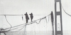
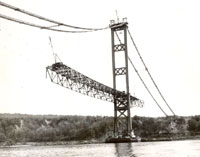
Salvage, two fearless workmen walk the damaged cable, 1943 WSA, WSDOT records
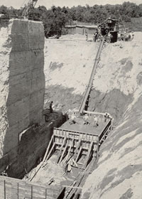
Salvage of the 1940 Narrows Bridge
After the center span fell into the Tacoma Narrows, the towers, main cables, side spans, and anchorages remained. The approach spans sustained no damage. The process of dismantling and salvaging the ruined bridge proved as intricate and dangerous as its construction.
In March 1941 estimates for salvage operations looked gloomy. Experts calculated the scrap metal value of the towers, deck floor system, and other steel parts at $206,000. It would cost three times that amount, an estimated $636,000, to dismantle the bridge. Dismantling of the towers began on September 8, 1941. With the start of World War II in December that year, hopes rose that a steel shortage would bring a better price, and perhaps a profit.
That hopeful vision faded. By the end of March 1943 workers had removed more than 4,000 tons of steel from the towers and 3,000 tons from the cables and deck. The salvaged metal was sold for scrap during World War II. In the end, salvage operations lost money. The Toll Bridge Authority paid nearly $646,661 for the effort. In return for 7,000 tons of scrap steel the State received a meager $295,726. The net cost for the operation was $350,933.
Interestingly, the process took about 29 months, roughly the same amount of time that it would take to build the replacement Narrows Bridge at the end of the decade.
Engineering challenges For Gertie's Replacement
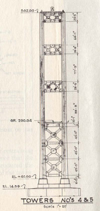
Tower face drawing, Current Narrows Bridge WSA, WSDOT records
Engineers faced two major challenges in building the second (current) Narrows Bridge. First, they had to better explain what happened to the 1940 bridge, and to design one that would not meet the same fate. Second, what remnants of the old bridge, especially the piers, could be used?
In July 1941 Charles E. Andrew, consulting engineer for the Washington State Toll Bridge Authority (WSTBA), appointed Dexter R. Smith as chief design engineer to plan the new structure. By October the state had a new design. The plans roughly resembled Clark Eldridge's original design. The proposed replacement bridge with a deep, open deck truss would cost about $7 million.
The proposed design for the new Narrows Bridge needed testing. Issues of aerodynamic stability in the design of suspension bridges had never before been investigated. Testing the bridge design fell to F. B. Farquharson, professor of engineering at the University of Washington. Dexter Smith and the State's bridge design team consulted extensively with Professor Farquharson and his research group at the University. Their work represented the leading edge. They were pioneering the field of bridge aerodynamics.
For the four years of World War II, and occasionally afterwards to 1947, Farquharson studied the 1940 span and the new proposed Narrows Bridge in a specially built, 100-foot long Structural Research Laboratory that housed a wind tunnel and scale models of the bridges.
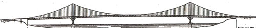
1950 Narrows Bridge, elevation sketch WSDOT
First, Farquharson confirmed that the 1940 Narrows Bridge had collapsed because of its excessive flexibility and susceptibility to aerodynamic forces. Galloping Gertie became the first suspension bridge ever studied using both visual observation and wind tunnel testing. These investigations laid the foundation for continued research. If a dynamic scale model of a proposed bridge design could pass Farquharson's wind tunnel testing, then Smith and his bridge engineers could build the real thing with confidence at the Tacoma Narrows.
They envisioned a new Narrows Bridge designed to offer the least wind resistance. The solution would be to use deep, open stiffening trusses with trussed floor beams. The truss members would be shallow, to avoid creating any large, solid surfaces like the ones associated with the failure of the 1940 Narrows Bridge.

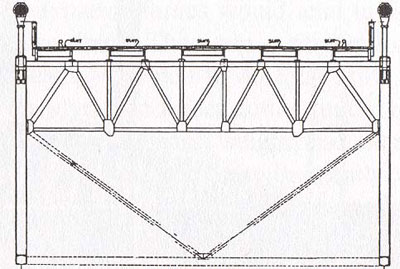
Warren truss of the 1950 Narrows Bridge, sketch WSDOT
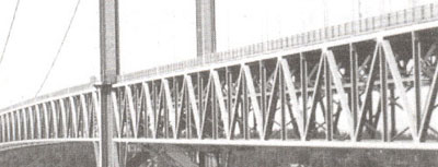
View of 1950 Narrows Bridge's 33-foot deep Warren truss WSDOT
Farquharson built a 1:50 full scale model and sectional models of Smith's design. The tests included subjecting the model to wind forces striking the bridge at angles up to plus-and-minus 45 degrees perpendicular to the deck. This wide range of wind angles helped give the new bridge design even greater stability. (Today, design engineers typically use a narrower range of plus-to-minus 5 degrees.) The tests proved that the proposed bridge would be far more stable than Galloping Gertie. Farquharson decided to test the model equipped with open wind grates to permit freer airflow and minimize the wind's effects. It worked. The model now showed virtually no torsional movement.
Smith and Farquharson decided to take additional steps. They wanted to eliminate as much vertical and twisting motion in the model as possible. Mechanical devices would enhance their design's natural damping ability. First, they added a double lateral bracing system to the stiffening truss to increase torsional stiffness. Second, they added hydraulic shock absorbers at three strategic points in the structure: at mid-span, between the main span and side span, and at each tower.
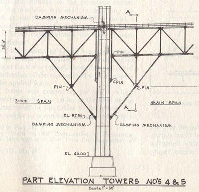
Tower & deck cross-section showing damping mechanism, Current Narrows Bridge WSA, WSDOT records
The existing piers posed the second engineering challenge. Would they support the proposed four-lane bridge, which was 60 percent heavier than the old superstructure? The piers had been stressed by collapse of the 1940 bridge, as well as by 17 earthquakes that struck the area between 1939 and 1946. Two of those reached 5 on the Richter scale. Engineers discovered, to their relief, that the piers would prove to be solid foundations for the heavier new span.
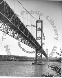
Current Narrows Bridge, view from beach level, September 26, 1950. The copyright in this image is the property of the Tacoma Public Library. Any additional copies or reproduction of this image are prohibited. All rights reserved
The tests from 1941 to 1947 cost over $88,000 when completed. By comparison at the time, a pound of coffee cost 29 cents, and you could buy a new car for about $1,500, or rent a 3-room duplex for $50 a month. But, the extensive investigations gave the State's engineers confidence in their new design. The proposed bridge would stand safe and solid in winds up to 127 mph for a 3-second gust.
An "epoch-making" new span rises
Thanks to the failure of its predecessor, Galloping Gertie, the current Narrows Bridge affected the course of suspension bridge engineering and design. The years of research into aerodynamics, and the new mathematical knowledge of vibrations and wave phenomena ushered in a new era of more stable suspension spans.
The next generation of large suspension bridges featured deep and rigid stiffening trusses. Completion of the 1950 Narrows Bridge was soon followed in the United States by the Delaware Memorial Bridge in 1951, the Chesapeake Bay Bridge (Preston Lane Jr. Memorial Bridge) in 1952, and David Steinman's great Mackinac Strait Bridge, built from 1954 to 1957.
"Epoch-making," is how one writer describes the current Narrows Bridge. It represented a remarkable achievement. Its design, engineering, functions, and stability were unprecedented. Its aesthetic appeal marked a milestone as well. The visually stunning "Sturdy Gertie" helped shift popular perceptions about "beautiful" suspension bridges.
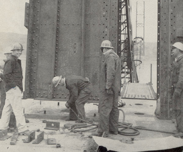
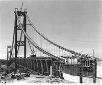
Setting tower base plate, 1948 WSDOT
Construction began on April 8, 1948. The contract for steel fabrication and erection went to Bethlehem Pacific Coast Steel. John A. Roebling Sons Company won the cable spinning contract. Some 29 months later, the bridge opened to the public on October 14, 1950. Once again, the Tacoma Narrows became home to the third longest suspension bridge in the world.
Overall, the 1950 Narrows Bridge has a suspended structure of 5,000 feet--a center span of 2,800 feet and two side spans of 1,100 feet (the same as its predecessor, since the same piers were used). The motion damping devices tested in Farquharson's wind tunnel all appeared in the finished bridge.
The new four-lane bridge had several features that made it 58 times more rigid than the 1940 Narrows Bridge. They immediately earned the span a distinctive place in bridge engineering history. In 1950 the Tacoma Narrows Bridge was the most technically advanced long span suspension bridge in the world.
Innovations & Special Features:
- The deck system's prominent 33-foot deep steel Warren stiffening trusses: These gave the bridge a depth-to-center span ratio of 1 to 85, the deepest stiffening system on a major suspension span since the 1909 Manhattan Bridge.
- Double (top and bottom) lateral bracing of the stiffening trusses:
This feature, combined with the 33-foot deep stiffening truss, gave the bridge exceptional torsional rigidity. - Wind grates:
Three slots of open steel grating 33 inches wide separating all four traffic lanes, and a strip 19 inches wide along each curb. - Hydraulic shock absorbers at three strategic points in the structure:
(1) at mid-span, at the main cable center tie, between the main suspension cables and the top of the stiffening truss; 6 devices per cable (a "first" for a long suspension bridge
(2) between the top chords of the main span and side span stiffening trusses; and
(3) at each tower, where it joins the bottom of the deck truss. - Ends of the west and east side spans were anchored securely to the ground.
- Cable sag ratio of 1:12. This required the towers to be higher than the 1940 bridge, which had a sag ratio of 1:10.
Fire, ice, and earthquakes
Engineering challenges were not the only difficulties faced by the builders of the 1950 Narrows Bridge. Some of the reasons that construction took 29 months had to do with several challenges from "Mother Nature."
On April 13, 1949 an earthquake measuring 7.1 on the Richter scale shook the Puget Sound region. The trembler caused no damage to the Narrows Bridge's piers or towers, then under construction.
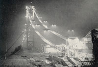
The severe winter of 1949-50 slowed construction. Engineers already had concerns about starting cable spinning in the coldest season. That winter proved their worries valid. For six weeks rain and snow, driven by high winds, lashed the area. Once, ice an inch thick had to be removed from steel so men could do their jobs. Especially rough was work on the cable spinning. At times, workers had to use blowtorches to thaw out cable strands for adjustment and banding. By February 1950 the cable spinning contractor, John A. Roebling Sons Co., was fighting a 2-month delay.
Who were the engineers and bridge workers who endured these hardships and successfully met the challenges? You'll find the two main engineers who launched the 1950 Narrows Bridge, Charles Andrew and Dexter R. Smith. Take a look at a couple of the bridge workers, Earl White and Joe Gotchy.
Components of the Current Narrows Bridge
Piers
The piers designed by Clark Eldridge for Galloping Gertie stood ready to handle the new span's towers. The twin steel legs of each tower were 60 feet apart, center-to-center. The original pedestals were too narrow for the new towers. They were also too close to the water. In Gertie's short life, the tower legs showed signs of salt water corrosion. The new pedestals were the same width, but taller by 18 feet to keep the tower legs safe from salt spray. This pushed the height of the towers on the new span to 58 feet higher than those on the 1940 Narrows Bridge. The additional weight of the superstructure (1.6 times the load carried by the original piers) actually was better, more evenly distributed by the greater width between tower legs. The new design increased the dead load pressure on the piers by only 6 percent.
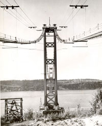
Towers with catwalks, 1949 WSDOT
Towers
Tower erection used a "crawler crane," which advanced upward as workers completed each tower leg. The legs of each tower are vertical. They are made of hollow steel cells, stacked on top of one another. The cell sections are four columns arranged to form a hollow core in the center. Each section is 32 feet long and weighs 27 tons. Viewed in cross-section, the four cells in each leg form a cross shape. To stabilize the towers during construction, temporary "outriggers" were added until the cables and deck trusses could be completed. When the top cross bracing was completed, Chicago booms hoisted the 28-ton cast-steel cable saddles and placed them at the top of each leg. The cable saddles were secured by 36 bolts.
Anchorages
Anchorage construction, 1948 WSDOT
Anchorage view with cable and eye-bars, 1949 Earl White
The new bridge had a much bigger cable load, increased from the original 28 million pounds to 36 million pounds. This required modification of the anchorages for the 1940 bridge. The old anchorages, spaced 39 feet apart, were retrofitted for the new span's 60-foot spacing between cables. The original structures became the cores of the new, heavier and wider 54,000-ton anchor blocks. The anchorages included 62-foot long eye-bars, fitted with 26-inch diameter shoes, embedded into the new concrete.
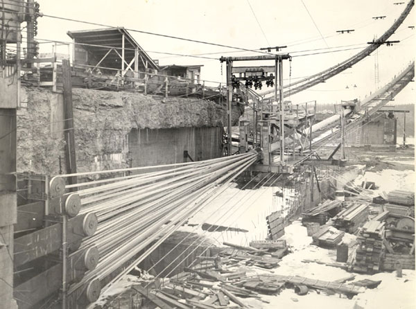
Cables
Once the towers and cable saddles were in place, spinning began for the 20-1/4 inch diameter main suspension cables. Spaced 60 feet apart, each cable contained 19 strands of 458 No.6 gauge wires. The strands looped around the eye-bar shoes to form a continuous cable from anchorage to anchorage.
Deck
The 33-foot deep Warren stiffening truss system was assembled at the bridge site from shop-fabricated components. Four rolling derricks (2 per tower) moved each way from the tower. Two riveting crews and traveler operators worked from the tower piers to the center of the main span, while two other crews worked from the piers to the shore. First, workmen placed the top and bottom chords and their diagonal bracing. Next, the floor beams were placed between the chords. Then, deck stringers were laid lengthwise on top of the beams. Finally, crews pinned the members in place, and the riveting gangs finished the process.
Deck cross-section, Current Narrows Bridge WSA, WSDOT records
The deck measures 46 feet 9 inches (curb-to-curb) for the 4 traffic lanes, plus two sidewalks 2 feet 9 inches wide. Steel reinforcing rods were placed in the roadway. Then, workmen placed the deck slab, a light-weight concrete 5-3/4 inches thick with a 5/8-inch asphalt riding surface (used to lessen the load on the piers). The open steel wind grates were installed between driving lanes and at the curbs.
Suspender Cables and Cable Bands
As each section of the deck was assembled, crews hung the suspender cables. Each set of two cables, looped over the main cable appears to be four wires. These 1-3/8 inch diameter wire cables were attached to the deck at 32-foot intervals by zinc "jewels."
Special features & motion-damping devices
Finally, workmen installed the mechanical motion-damping devices.
Sand blasting and painting
The current Narrows Bridge is painted "Narrows Green." Sub-contractor for the bridge's first coat of green was H. P. Fisher & Sons Company of Seattle for painting the suspender cables, cable bands, and various steel parts.
"Span stats" – Statistical profile of the 1950 Narrows Bridge
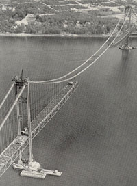
Deck construction, aerial view, spring 1950 WSDOT
- Total structure length - 5,979 feet
- Suspension bridge section - 5,000 feet
- Center Span - 2,800 feet
- Shore Suspension Spans (2), each - 1,100 feet
- East Approach and Anchorage - 365 feet
- West Approach and Anchorage - 614 feet
Anchorages: Current Narrows Bridge
Deck construction, view from water level, spring 1950 Earl White
- Weight of each anchorage (shore anchors) - 66,000 tons
- Concrete in each anchorage - 25,000 cu. yds.
- West Anchorage (concrete anchor block and gallery) - 164 feet long
- East Anchorage (concrete anchor block and gallery), plus approach, administration buildings and toll house - 185 feet long
- West Anchorage, construction & cost - Woodworth & Co. - $406,000 (est)
- East Anchorage, construction & cost - Woodworth & Co. - $386,000 (est)
Piers: Current Narrows Bridge
Last stages of construction, June 1950. The copyright in this image is the property of the Tacoma Public Library. Any additional copies or reproduction of this image are prohibited. All rights reserved
- West Pier, total height - 215 feet
- West Pier, depth of water - 120 feet
- West Pier, penetration at bottom - 55 feet
- East Pier, total height - 265 feet
- East Pier, depth of water - 135 feet
- East Pier, penetration at bottom - 90 feet
- Area - 118 feet, 11 inches by 65 feet, 11 inches
Cables: Current Narrows Bridge
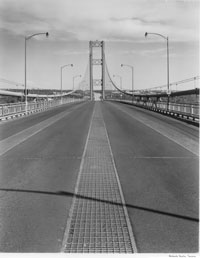
Roadway view of open grating, June 1951. The copyright in this image is the property of the Tacoma Public Library. Any additional copies or reproduction of this image are prohibited. All rights reserved
- Diameter of Main Suspension Cable - 20.25 inches
- Weight of Main Suspension Cable (each) - 5,441 tons
- Weight Sustained by Cables - 18,160 tons
- Number of No. 6 Wires in Each Cable - 8,705
- Total Length of Wire - 104,094,390 feet, = 19,715 miles
- Sag Ratio - 1:10
Towers: Current Narrows Bridge
- Height above water - 500 feet
- Height above piers - 467 feet
- Height above roadway - 280 feet
- Weight of each tower - 2,675 tons
- Night work to complete the bridge on time, 1950 WSDOT
Roadway - deck: Current Narrows Bridge
- Center Span height above water - 187.5 feet
- Weight of center span - 7,250 lb./ft
- Traffic lanes - 4
- Width of roadway - 49 feet 10 inches
- Width between cables - 60 feet
- Width of sidewalks(2), each - 3 feet 10 inches
- Number of girders and type - 2 Warren trusses
- Depth of girders - 33 feet
- Suspender cables - 32 foot intervals
- Thickness of roadway - 6-3/8 inch reinforced concrete
Span ratios
| Bridge | Width to Length (of Center Span) | Girder Depth to Length (of Center Span) |
|---|---|---|
| 1940 Narrows Bridge | 1:72 | 1:350 |
| Current Narrows Bridge | 1:46 | 1:112 |
| Golden Gate Bridge | 1:47 | 1:168 |
| George Washington Bridge | 1:33 | 1:120 |
| Bronx-Whitestone Bridge | 1:31 | 1:209 |