|
PGSuper
5.0
Precast-prestressed Girder Bridges
|
|
PGSuper
5.0
Precast-prestressed Girder Bridges
|
In this section you will about standard loads, user defined loads, and vehicular live loads.
Standard loading conditions are automatically generated. These loading conditions include:
Dead loads are based on cross sectional area of the members and the material unit weight. See the Structural Analysis Models section of the Technical Guide for a detailed explanation of how loads are generated and applied to the structural analysis models.
A construction load allowance carried by the non-composite girder section can also be defined. This allowance covers additional loads incurred by the use of stay-in-place metal forms or other permanent construction materials and tolerances. This loading is applied to the entire bridge deck and is distributed to each girder based on its tributary area. This loading is applied to the DC load case.
Certain permanent loads are applied to the composite bridge section. These loads must be distributed to the individual girders for analysis.
The dead load of the railing system (barriers and sidewalks) are distributed to the "N nearest Girders, Mating Surfaces, or Webs as defined in the Project Criteria.
The magnitude of the overlay load is computed using the overlay width, thickness, and density of the overlay material. The load is distributed as specified in the Project Criteria.
Vehicular live load is distributed to the girders in the bridge using live load distribution factors.
Pedestrian live load is distributed in the same manner as sidewalk dead load.
In addition to the standard loading, ad-hoc user defined loads can be modeled. These loads can represent anything, such as the dead load of a bridge mounted sign or other such appurtenances. Three different types of user-defined loads can be modeled: Point (concentrated), Linearly Distributed, and Moment. Loads are applied to individual girders and are not distributed to other elements of the structure.
User defined loads can be modeled by selecting Loads > Add Point Load, Loads > Add Distributed Load, or Loads > Add Moment Load. These loads can also be created and managed in the Loads view. Select Loads > Edit User Defined Loads to open the Loads view.
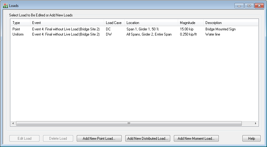
User defined loads can also be created and edited in the Girder View.
The standard HL93 design live load is automatically defined. You can define additional vehicular live load models in the Vehicular Live Load library. For design and specification compliance checking live loads are selected for the following limit state categories:
Select Loads > Design Live Loads to open the Design Live Loads window. In this window, select the live loads that will be used for design and specification compliance checking. When more than one live load model is selected in a limit state category, the live load responses for each model are enveloped and the controlling values are used for analysis.
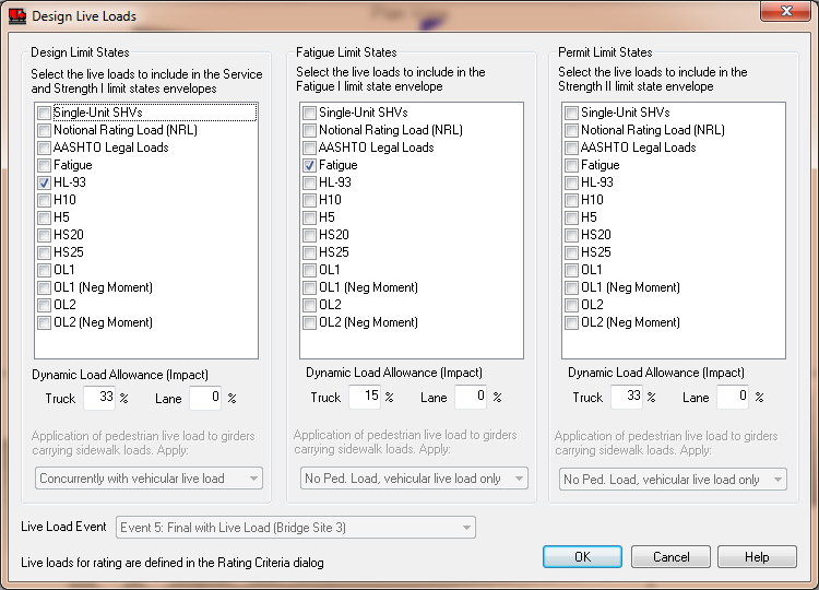
Pedestrian loads on sidewalks are automatically generated if the loading is enabled in the Design Live Loads window. Pedestrian live loads may be applied concurrently with or enveloped with vehicular live load.
NOTE: Live loads for load rating are defined in the Load Rating Options window.
 1.8.16