|
PGSuper
5.0
Precast-prestressed Girder Bridges
|
|
PGSuper
5.0
Precast-prestressed Girder Bridges
|
This chapter describes the Girder Designer, which provides automated girder design capabilities.
If you know everything about your structure at the beginning of a project all you have to do is verify it satisfies the LRFD Bridge Design Specification. However, when designing a new structure, life isn't quite so simple. It is your job as the designer to determine many of the attributes of your bridge and its precast-prestressed girders. This is where the Girder Designer comes in.
NOTE: The Girder Designer is not available when losses are computed by the Time-Step method.
Given a general bridge configuration, girder type, framing plan, and material information, the Girder Designer can make a really good estimate at what the other input parameters should be, including number and configuration of prestressing strands, jacking force, concrete strengths, transverse reinforcement and other bridge data. The Girder Designer can evaluate temporary construction conditions including stability during lifting girders from the casting bed and hauling them to the bridge site.
The flow chart below outlines the typical design process.
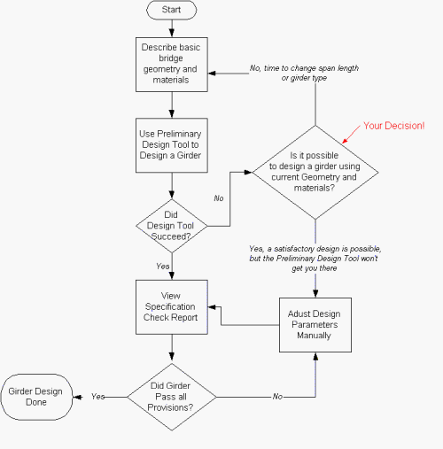
There are many parameters involved when designing a precast girder bridge superstructure, including girder spacing, girder size, span length, slab depth, slab overhang width, and concrete strength. In the most general case, you could say, "There's a hole in the ground, design a bridge that spans it". As you can see, design is a very open-ended activity.
The Girder Designer has a more narrow scope. Given basic bridge configuration information, it will make an estimate at what some of the input parameters should be. The Girder Designer can design for flexure and shear.
For flexure, the Girder Designer can determine:
For shear, the Girder Design can determine:
This section will discuss the mechanics of designing a girder. In practice, designing a girder can be very complex and tedious. In most cases, the Girder Designer does the hard work.
To use the Girder Designer:
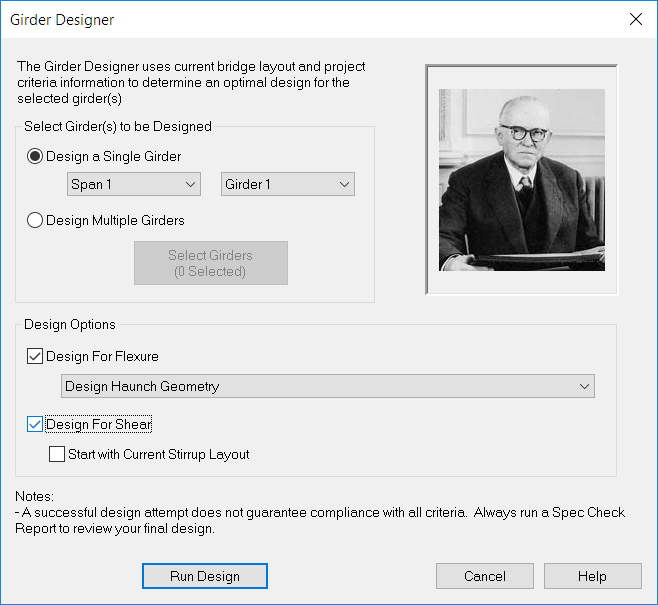
TIP: You can quickly design a girder by right clicking on it in the Bridge View or the Girder View, and Design Girder from the context menu. The girder will be designed using the most recently set options in the Girder Designer window.
When the design finishes, you will be presented with the Design Outcome report.
Before you accept design, it is prudent to carefully review the Design Outcome Report. The Design Outcome Report shows a comparison between the parameters that currently define a girder and the once the Girder Designer has determined.
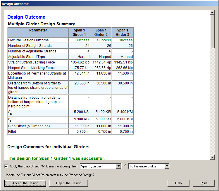
After reviewing the Design Outcome Report, you must decide to accept or reject the Girder Designer's proposed design. Press [Accept the Design] to accept the proposed design and update your bridge model. If you do not want to change your bridge model, press [Reject the Design].
NOTE: If a slab offset design is selected when designing multiple girders, you will be prompted to select which slab offset design to use for each, or all of the girders in the bridge as shown in the bottom of the figure below. PGSuper will check your haunch design, but formulation of a global slab offset design for all girders in your bridge is left up to you, the engineer.
TIP: Always run a full specification check (Details Report, or Spec. Check Report) after running a design. Approximations made by the Girder Designer may not satisfy all of the project criteria or the LRFD requirements.
TIP: The Girder Designer is very good, but not perfect. It may fail even if a successful design is possible. Or, it might be possible to create a "better" design by defining your own girder input, reviewing results, and modifying girder data manually.
For most prestress girder designs, strands and/or material properties must be adjusted in order to meet stress requirements near the ends of a girder at release. We refer to this as Prestressing Optimization. The Girder Designer's strategies for prestressing optimization fall into these basic categories:
The choice of one or more optimization strategies depends on the girder type, economic preferences, safety, or other concerns in your local area. For example, local precasters might prefer debonding over harping: So for I-girders an agency might first want to attempt an all-straight fully bonded design using a high strength concrete; if that fails, try a design using debonding and normal strength concrete; and if that fails, try a harped strand design.
Prestress Optimization strategies are configured on the Flexural Design tab in Girder Library entries as shown below. Here, you can configure the Girder Designer to attempt different types of prestressing designs in the order shown.
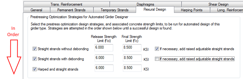
The design strategies are attempted in the order shown. When a strategy fails, the Girder Designer will proceed to the next strategy until all have been exhausted. Each design strategy has concrete strength limits that define the maximum values of the release and final concrete strengths. If the design requires concrete strengths in excess of these limits the Girder Design will move on to the next strategy.
TIP: The more strategies you select, the longer it may take to complete a design.
Stress analysis can be based on gross or transformed section properties. When transformed section properties are used the area, centroid, and section moduli of the girder change with both time (properties use a modular ratio of Eps/Eci at release and Eps/Ec at final) and the number and configuration of the strands. Concrete strength and strand arrangements are constantly being optimized during the design process causing section properties to change at each iteration. As you can imagine, convergence on a design when transformed section properties are used can be challenging.
When stress analysis is based on transformed section properties, the girder design is based on the section properties at the beginning of the design. Section properties are not updated during design.
To further optimize your design,
TIP: The option whether to use transformed or gross section properties is selected in the Project Criteria, General tab.
 1.8.16