|
PGSplice
4.1
Precast-prestressed Spliced Girder Bridges
|
|
PGSplice
4.1
Precast-prestressed Spliced Girder Bridges
|
The LRFD specifications required that prestress losses in post-tensioned spliced precast girders be determined by the time-step method. The time-step method can also be used for precast prestressed girders when a rigourous analysis is required.
From LRFD 5.9.3.4.1 (pre-2017: 5.9.5.4.1):
For segmental construction and post-tensioned spliced precast girders, other than during preliminary design, prestress losses shall be determined by the time-step method... including consideration of the time-dependent construction stages and schedule shown in the contract documents.
For components with combined pretensioning and post-tensioning, and where post-tensioning is applied in more that one stage, the effects of subsequent prestressing on the creep loss of previous prestressing shall be considered.
The time-step analysis method models the design life of a structure through discrete intervals of time. The deformations, stresses, and internal forces that develop in response to external loads and time-dependent material effects are computed for each time interval. The time-dependent material effects include changes in concrete strength and elastic modulus as a function of time, creep and shrinkage of concrete, and relaxation of prestressing strands. The response of the structure at the end of any time interval is taken to be the summation of the responses of the preceding intervals.
Conceptually, time-step analysis is a straightforward method based on fundamental principles of engineering mechanics. The method of time-step analysis discussed below was originally presented by Tadros, et.al.1 in 1977. A summary will be presented that focuses on the key elements of the analysis method. The challenge of time-step analysis is the enormous quantity of calculations that must be performed. Several factors contribute to the computational burden of this method. Concrete strength, and thus the modulus of elasticity, increases as a function of time resulting in different transformed section properties in each time interval. Spliced girders are often non-prismatic with deeper sections at intermediate piers than in the main spans. Tendon profiles typically have varying eccentricities which further compounds the computation of section properties. Creep strain rates change as a function of time and incremental loading. Shrinkage strain and strand relaxation rates also vary with time. The sheer quantity of calculations that must be performed for a rigorous time-step analysis make computer aided design the only feasible option.
Precast concrete spliced girders are a composition of precast concrete segments, cast-in-place closure joints, a cast-in-place concrete deck, strands, tendons, and reinforcing bars. The parts of a spliced girder can be classified into three distinct materials; concrete, prestressing steel, and nonprestressed reinforcing bars. Concrete has a time-dependent stress strain relationship because of creep and shrinkage. Prestressing steel has a time-dependent stress strain relationship due to relaxation. Nonprestressed reinforcement is assumed to be a linear elastic material obeying Hooke's law.
Any suitable time variation relationship for elastic modulus, creep, shrinkage and relaxation can be used in the time-step analysis. AASHTO LRFD provides general relationships for elastic modulus, creep and shrinkage that can be used in lieu of project-specific material data. However, AASHTO LRFD does not provide time variation relationships for the strength of concrete or intrinsic relaxation of prestressing steel. AASHTO LRFD permits the use of the time variation relationships from American Concrete Institute Committee 209 (ACI 209) and the CEB-FIP Model Code (CEB-FIP).
A mathematical model of time is central to the time-step analysis method. A sequence of discrete time intervals is used to model the design timeline. The duration of each interval is determined by the time at which changes in loading and the statical structural system are assumed to occur. Suddenly applied loads (e.g. prestress force, self-weight, and superimposed loads) and sudden changes to the statical structural system (e.g. removal of temporary supports) are assumed to cause an instantaneous response in the structure at a specific time. Because the time-dependent material responses are most appreciable immediately following a sudden change in internal resisting forces the timeline is further divided into small time intervals following the load application. The length of intervals can be increased progressively as time goes on. Time dependent changes are continuous during an interval. The total change in loading during an interval is assumed to occur at the middle of the interval and that the duration of intervals when sudden changes occur is zero. The design timeline generally begins when the first pretension strand is stressed and concludes at the end of the design life of the structure.
The time-step method analyzes deformations, stresses, and forces in each part of a spliced girder as a summation of the incremental responses in the preceding intervals. The incremental deformations, axial strain (De) and curvature (Df), of each part of the spliced girder during the ith interval are presented below. The variables i and j represent the ith and jth interval. The subscripts b, m, and e, represent the beginning, middle, and end of the interval, respectively. DP and DM are changes in axial force and moment on the composite spliced girder section or on the individual part when accompanied by a subscript. A and I are the net cross sectional area and moment of inertia about the centroid of the part. E is the elastic modulus of the part. The subscripts indicate the cross section part type (c = concrete, ps = prestressed reinforcement, ns = nonprestressed reinforcement, and k = the kth part). y is the ratio of creep deformation at the end of an interval to the instantaneous deformation caused by the sustained loading introduced in the middle of a previously occurring interval.
The incremental deformations in concrete parts of a spliced girder can be obtained from Equations (1) and (2).

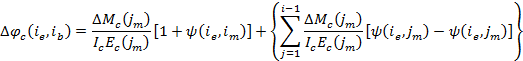
The first term in Equations (1) and (2) represent the elastic and creep deformations due to incremental loads that occur during the interval. The terms inside the braces are "initial deformations" which are deformations that are independent of the stress introduced during the interval. For concrete parts the source of initial deformation is creep and shrinkage.
The first term in the braces represents the increment of creep deformation for all loads introduced prior to the current interval. The operand of the summation is the deformation that occurs during interval i due to a load introduced at the middle of interval j.
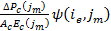
A deeper examination of the operand of the summation in Equation (1) reveals

is the axial strain caused by a load increment on the concrete part occurring at the middle of interval j where DPc(jm) is the incremental axial force on the concrete part, Ac is the net area of the concrete part and Ec(jm) is the modulus of elasticity of the concrete part at the middle of interval j.
is the creep strain at the end of interval i due to loading applied at the middle of interval j.
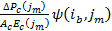
is the creep strain at the beginning of interval i due to loading applied at the middle of interval j. Hence,
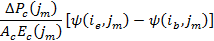
is the change in creep strain occurring during interval i due to a load increment occurring at the middle of interval j.
Similarly, the summation in Equation (2) is the incremental curvature occurring during interval i due to load increments that occurred at the middle of the previous intervals.
The last term in the braces of Equation (1) is the incremental shrinkage strain occurring during the interval.
Assuming the flexural rigidity of prestress steel parts is negligible compared to the overall composite cross section; the incremental deformation is limited to axial strain and can be obtained from Equation (3).
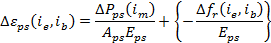
The first term in Equation (3) is the elastic deformation of the prestressing steel due to incremental loads that occur during interval i. The term inside the braces is the time-dependent deformation due to relaxation where Dfr is the reduced relaxation occurring during interval i. This is also an "initial deformation".
The intrinsic relaxation of prestressing steel is determined from tests in which the steel tendon is stretched between two fixed points. The length of the test specimen remains constant. However, as part of a composite concrete member, the reduction in steel stress due to shortening of the tendon results in a reduced relaxation compared to the intrinsic value.
Various empirical equations expressing the intrinsic relaxation as a function of time and initial stress are available2. The shortening of the tendon in a composite concrete member is a function of the change in stress due to the various sources of incremental load and the relaxation that occurs during an interval, neither of which is known. An iterative procedure is needed to determine the reduced relaxation during an interval.
A suitable approximation of the reduced relaxation can be obtained by substituting the effective stress in the tendon at the beginning of the ith interval into the intrinsic relaxation equation. This approximation avoids a substantial increase in computation time. The error is relatively small, especially for short intervals. Relaxation is the least significant of the time dependent effects so a high degree of accuracy is not warranted.
The incremental deformation of nonprestressing steel parts is also limited to axial strain when assuming the flexural rigidity of the part is negligible.
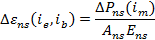
The deformation in non-prestressed steel is given by Equation (4) and is simply the deformation due to loads that occur during this interval.
Equations (1) through (4) require the incremental loading on the various parts of the spliced girder due to the overall change in loading on the composite section. Using transformed section analysis, the change in force in the kth part of the cross section due to the loading increment, DP and DM, is obtained from Equations (5) and (6).
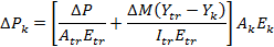
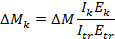
Atr, Itr, and Ytr are the cross sectional area, moment of inertia about the centroidal axis, and the location of the centroid, respectively, of the transformed composite section based on the modulus of elasticity, Etr, at the middle of the interval when the loading is applied. Ak, Ik, and Yk are the cross sectional area, moment of inertia about the centriodal axis, and the location of the centroid, respectively, of the kth part based on its net section. Ek is the modulus of elasticity of the part's material.
Analysis for the effects of initial deformations can be performed in the same manner as solving for the effects of temperature change. Secondary actions (moments, shears, axial forces, and reactions) result whenever deformations that would normally occur are prevented. The internal stress that develops as a result of initial deformations is analogous to the internal stress due to the secondary effects of post-tensioning.
It is convenient to consider two circumstances under which these stresses occur; 1) conditions such that there would be no stresses except for the constraint of external forces and 2) stresses that are produced in the absence of external constraint solely because of the incompatibility of the deformations of the different parts of the element3. Stresses in the first circumstance may be found by determining the deformations that would occur if the system were unconstrained and then imposing those deformations on the constrained system. The deformations that would occur in the unconstrained system are found by analyzing the second circumstance.
The deformations of the unconstrained system are determined by applying an artificial restraining force to the kth part to prevent its deformations ek and fk, which are the axial strain and curvature that would occur if the part was free to deform. Internal stresses will develop. At any section of the kth part, the stress resultants are

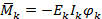
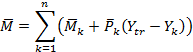
For the whole composite section consisting of n parts the initial deformation stress resultants are

The deformations at each section of the unrestrained system are


The continuous deformation of the unrestrained system is approximated with section deformations at regularly spaced intervals assuming a linear variation between sections. The bridge frame is analyzed for these deformations. The results of the analysis give the incremental displacement of the restrained structure as well as the incremental internal stress resultants for the interval under consideration.
The incremental internal stress resultants are proportioned to the various parts of the spliced girder with Equations (5) and (6). These stress resultants are incremental loads that cause creep in the concrete parts that is in addition to the creep caused by suddenly applied loads and changes to the statical structural system. The incremental forces on the concrete parts due to initial deformations are accounted for in the first term of Equations (1) and (2) during the interval when the forces first develop and in the summation in subsequent intervals.
 1.8.16