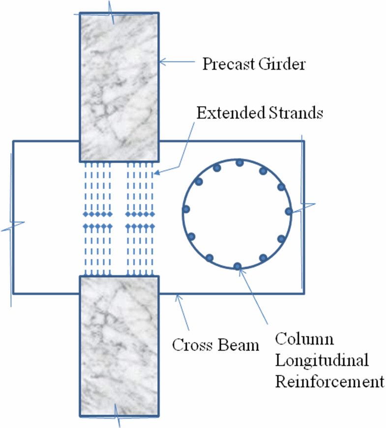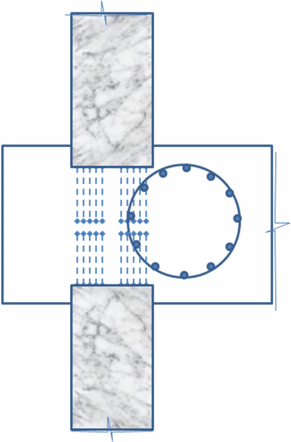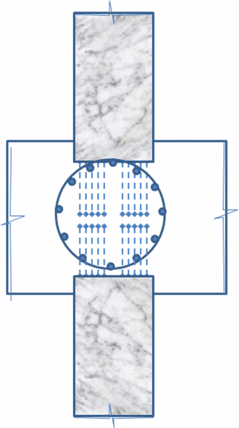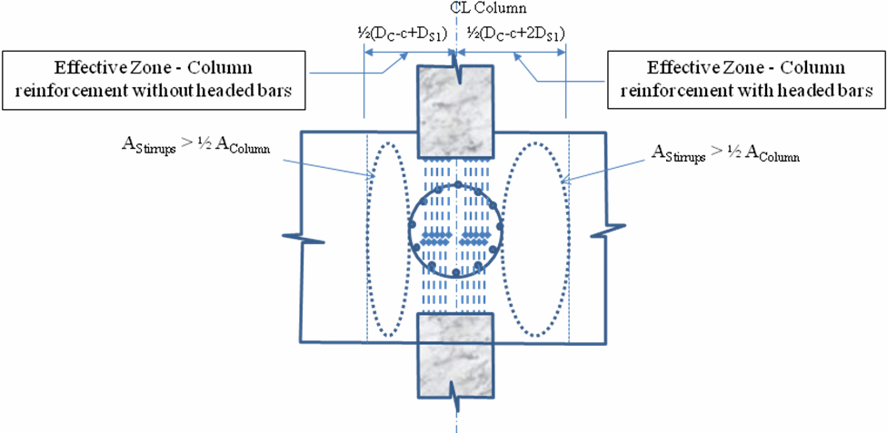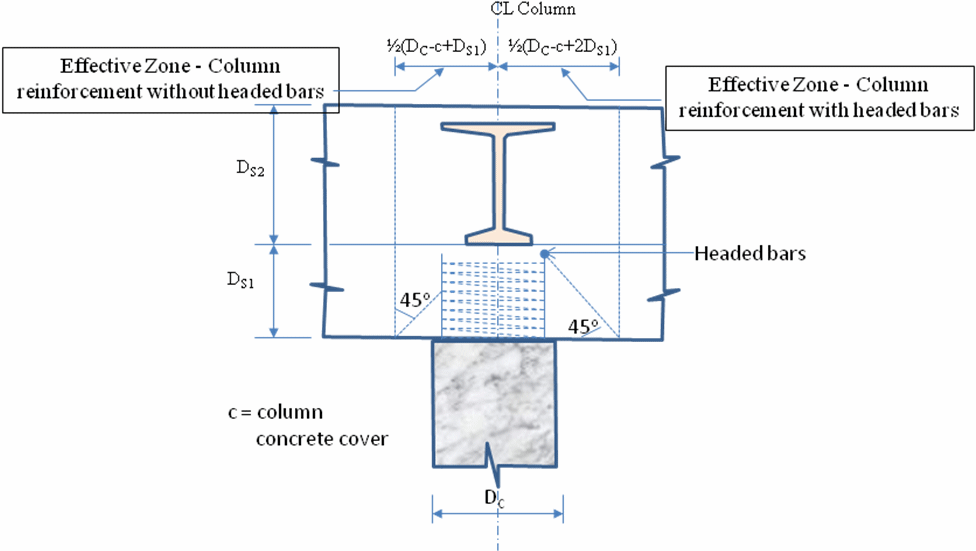
This policy requires that for precast prestressed concrete girder bridges in SDCs C and D with two-stage fixed diaphragms at intermediate piers, all column longitudinal reinforcement shall extend to the top of the cast-in-place concrete diaphragm (upper crossbeam) above the lower crossbeam. The column bars may be terminated just below the top mat of crossbeam reinforcement. If the column bars cannot be carried to the top of the upper crossbeam, additional reinforcement will be necessary to transfer seismic forces to the upper crossbeam. For bridges in SDCs A and B with fixed diaphragms at intermediate piers, column longitudinal reinforcement may be terminated at top of lower crossbeam in accordance with previous (?) practice, provided adequate transfer of column forces is provided. If column reinforcement is terminated in the lower crossbeam of a fixed intermediate diaphragm pier, a viable load path for expected tensile forces must be provided, regardless of SDC. This may be achieved by a non-contact splice between the column bars and the surrounding stirrups or supplemental hanger reinforcement, included solely to transfer column tensile forces. In SDCs A and B where full capacity protection is not included, the designer shall assure that unintentional weak links in the tensile load path do not exist between the upper and lower crossbeams. Careful attention should be made during design and pier orientation development that column reinforcement does not interfere with extended strands projecting from the end of the prestressed concrete girders. An adequate load path must exist regardless of whether the column moment is large enough for plastic hinging to occur. Examples of column longitudinal reinforcement interfering with the extended strands are shown in Figure 1. In case of interference, column longitudinal reinforcement obstructing the extended strands may be terminated at top of lower crossbeam, and shall be replaced with equivalent full-height stirrups extending from the lower to upper crossbeam within the effective width as shown in Figure 2. All stirrups within the effective zone, as shown in Figure 2 based on an approximate strut-and-tie model, may be used for this purpose. The effective zone shall be taken as column diameter plus depth of lower crossbeam provided that straight column bars are adequately developed into the lower crossbeam. The effective zone may be increased to column diameter plus two times depth of lower crossbeam if headed bars are used for column longitudinal reinforcement. If the depth of lower crossbeam is less than 1.25 times the tension development length required for column reinforcement, headed bars shall be used. Heads on column bars terminated in the lower crossbeam are preferable from a structural perspective. However, extra care in detailing during design and extra care in placement of the column reinforcement during construction is required. Typically the heads on the column bars will be placed below the lower crossbeam top mat of reinforcement. Headed reinforcement shall comply with ASTM 970 Class HA.
Transverse column reinforcement only need extend to the top of the lower crossbeam just below the top longitudinal steel. However, when the joint shear principal tension is less than 0.11√f’c, minimum cross tie reinforcement shall be placed acting across the upper cross beam in accordance with the SGS Article 8.13.3. The minimum cross tie reinforcement shall provide at least as much confining pressure at yield as the column spiral can provide at yield. This pressure may be calculated assuming hydrostatic conditions. If the joint shear principal tension exceeds 0.11√f’c, then additional joint reinforcement as outlined by the SGS shall be provided. With the exception of J-bars, the additional reinforcement shall be placed in both the upper and lower crossbeam. The cross tie reinforcement may be placed with a lap splice in the center of the joint. Large columns, or columns with high longitudinal reinforcement percentages, may result in closely spaced stirrups, with little clear space left for proper concrete consolidation outside the reinforcement. In such cases, either hanger reinforcement comprised of larger bars and heads may be used in the effective zone or supplemental stirrups may be placed beyond the effective zone shown in Figure 2. Hanger reinforcement in the effective zone is preferred. The designer is encouraged to include interference detail/plan views of the crossbeam reinforcement in relation to the column steel in the contract drawings. Suggested plans include the views at the lower stage crossbeam top reinforcement and the upper crossbeam top reinforcement.
AASHTO SGS Article 8.8.4 requires that for SDCs C and D, the column longitudinal reinforcement be extended into cap beams as close as practically possible to the opposite face of the cap beam. The performance of column-to-cap connection built using the previous WSDOT practice of column longitudinal reinforcement terminated at top of the lower crossbeam is uncertain due to lack of supporting experimental laboratory tests. This memorandum addresses the inconsistency between previous WSDOT practice and the AASHTO SGS requirements. To ensure adequate force transfer between the columns, crossbeam and superstructure, sufficient tensile reinforcement must exist to transmit the expected tension forces. Thus to prevent an unwanted plane of weakness between the column and superstructure for fixed diaphragm piers, either the column steel must extend to the top of the upper-stage crossbeam or additional reinforcement must be placed to transmit the expected tension forces via a non-contact lap splice. The cross beam stirrups adjacent to the column may be used to transmit the column tensile force to the upper crossbeam. This is acceptable for two reasons, 1) the column overstrength demand establishes the tensile force requirement for the non-contact splice, thus the crossbeam seismic shear and joint shear forces are likewise established by the column overstrength force level and 2) the gravity dead load shear effect acts opposite to the seismic tension effects (i.e. the dead load shear would normally induce compression not tension at the top of the column). However, the dead load shear cannot be used to reduce the tension force because the overstrength condition will result in the gravity shear being carried by the compression region of the column. If crossbeam stirrups are not adequate to carry the tensile force, then additional hanger reinforcement shall be used. Such reinforcement will typically be larger diameter bars, thus requiring heads on both their ends. Heads are not required on the stirrups due to their bends around the longitudinal crossbeam reinforcement. For large columns, or for columns with large main reinforcement percentages, it will be difficult to place enough stirrups into the space shown, resulting in closely spaced stirrups, with little clear space for proper consolidation of concrete outside the reinforcement. Consequently, the designer may need to use supplemental stirrups or hanger reinforcement in the effective area shown in Figure 2 to replace the column steel area. For the two-stage crossbeam configuration, placement of a spiral around the column bars in the upper crossbeam can be difficult. At the extra distance above the column plastic hinging zone provided by the lower crossbeam, joint force transfer spreads over a wider volume of crossbeam than for a flush-soffit girder and crossbeam arrangement. Consequently, the confinement of a spiral along the upper column is less effective and mobilization of the spiral would require cracking of a large volume of crossbeam concrete. For that reason the spiral need not extend into the upper crossbeam. However, an equivalent confinement pressure must be able to be mobilized, and this is provided by including a sufficient number of cross ties in the upper crossbeam to produce a similar confining pressure on the joint concrete volume to that the column spiral can develop across the column cross section. These cross ties need not be included between the projections of the girder faces. Because the joint is capacity protected and not expected to experience wide cracking as in the plastic hinging zone, the cross ties may be lap-spliced in the center of the cross beam to aid constructability.
Figure 1a: Column Longitudinal Reinforcement Interference with Extended Strands
Figure 1b: Column Longitudinal Reinforcement Interference with Extended Strands
Figure 1c: Column Longitudinal Reinforcement Interference with Extended Strands
Figure 2a: Column Longitudinal Reinforcement Termination
Figure 2b: Column Longitudinal Reinforcement Termination
|