Design Memorandum
TO: All Design Section Staff
FROM: Bijan Khaleghi
DATE: May 3, 2012
SUBJECT: SE Wall Supported Abutments
This design memorandum defines WSDOT policy for use of Structural Earth (SE) Wall Supported Abutments of single or multi span bridges. The SE wall supported abutments shall be designed in accordance with the requirements of the following documents:
- FHWA NHI-10-024 Volume I and NHI-10-025 Volume II, “Design and Construction of Mechanically Stabilized Earth Walls and Reinforced Soil Slopes,” (Berg et al., 2009)
- AASHTO (2012),”AASHTO LRFD Bridge Design Specifications, 6th Edition.
- WSDOT Geotechnical Design Manual section 15.5.3.5 for MSE Wall Supported Abutments.
- and this policy memorandum.
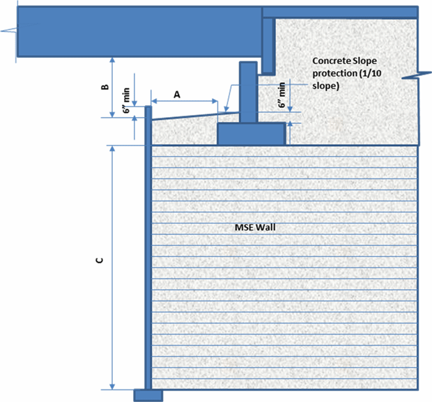
SE walls directly supporting spread footing bridge abutments shall be 30 feet or less in total height, retained soil height plus embedded depth, measured from top of leveling pad to bottom of spread footing. SE walls supporting bridge abutments shall be special designed wall systems. Abutment on spread footings shall be designed for bearing pressure at service loads not to exceed 2.0 TSF and factored load at strength and extreme limit states footing loads not to exceed 3.5 TSF. The bearing pressure may be increased to 3.0 TSF at service loads and 4.5 TSF at strength and extreme limit states if a vertical settlement monitoring program is conducted in accordance with WSDOT GDM section 15.5.3.5. Superstructure of continuous span bridges shall be designed for the differential settlements between piers. The following limitations, as shown in Figure 1, shall be considered when using SE Wall Supported Abutments. The limitations supersede the limitations of AASHTO LRFD Section 11.10.11:
- The front edge of the bridge footing shall be placed 4 feet minimum from the back face of the SE Wall fascia panels. The front edge of the bridge footing shall be placed 2 feet minimum for Geosynthetic walls with wrapped face.
- To provide bridge inspection access, the bottom of the bridge superstructure to top of slope protection surface shall be placed 3 feet minimum for I-girder type bridges, and 5 feet minimum for non I-girder, slab and box girder type bridges. Fall protection shall be installed as required by the appropriate WAC.
- The abutment footing shall be covered by 6 inch minimum soil for frost protection.
- The front edge of the bridge footing shall be placed 4 feet minimum from the back face of the SE wall fascia panel. This distance may be reduced to 2 feet minimum for Geosynthetic walls (wrapped face).
Only precast concrete panel faced SE walls or cast-in-place concrete faced SE walls may be used for permanent bridge installations. Precast concrete block faced SE walls and welded wire faced SE walls may be used for temporary bridge installations only.
Proprietary SE walls supporting abutments shall not be considered preapproved, and shall not be used beyond the limits described herein unless approved by the State Geotechnical Engineer and the Bridge Design Engineer.
Background:
Using SE structures as direct bridge abutments can be a simplification in the design and construction of bridge abutments and may lead to faster construction of bridges. Additionally, it could result in construction cost savings due to elimination of tall abutments. This solution would also contribute to better compatibility of deformation between the components of bridge abutment systems, thus minimizing the effects of differential settlements and the undesirable “bump” at bridge / embankment transitions, reducing the life cycle cost of the bridge.
If you have any questions regarding these issues, please contact Bijan Khaleghi at 705-7181 or by e-mail at: KhalegB@wsdot.wa.gov .
cc: Mark Gaines, Bridge Construction - 47354
F. Posner, Bridge and Structures – 47340

A. 4 feet min for SE Walls (precast concrete panel face or cast-in-place concrete face) and
2 feet min for Geosynthetic walls (wrapped face)
B. 3 feet min for girder bridges and 5 ft min for non-girder, slab, and box girder bridges
C. 30 feet max
Figure 1. Typical section – SE Wall Supported Bridge Abutment
Semi-integral abutment shown, L-abutment similar
Wing/Curtain Wall not shown
Note: Click here for a PDF of this design memo.
|

