Memorandum |
| TO: | All Design Section Staff |
| FROM: | Chuck Ruth |
| DATE: | August 8, 1997 |
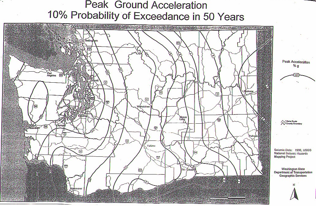
| SUBJECT: | Peak Ground Acceleration Map Used for Bridge Design |
The attached Peak Ground Acceleration Map replaces the current Velocity-Related
Acceleration Map (Figure 4.1.5-1) and supersedes my memo of August 10, 1995 (copy
attached).
The BDM will be updated at the next appropriate revision date as follows:
4.1.5 Earthquake Loads
d. Use the USGS Peak Ground Acceleration map (Figure 4.1.5-1, 10% Probability of Exceedance in 50 Years) to obtain an acceleration coefficient for preliminary design. The project Foundation Report will contain the acceleration coefficient for preliminary design to use in the final design of a bridge.. When using Figure 4.1.5-1, interpolate between contours to find the value to use for a particular site, and round to the nearest 1% of gravity(g). In general, Figure 4.1.5-1 can also be used for bridge seismic retrofit designs. However, seismic evaluation and retrofitting of older bridges can sometimes result in excessive costs (there retrofit costs are not consistent with the benefit gained). In these situations, the Bridge Design Engineer should be consulted for direction.
CCR
cc: (w/attach) M. M. Lwin
R. George
E. H. Henley
R. T. Shaefer
Y. Mhatre
K. Kirker
J. VanLund
Z. Fahoum
F. Higgins
T. Allen, 47365
B. Kimmerling, 47365